Download præsentationen
Præsentation er lastning. Vent venligst

1
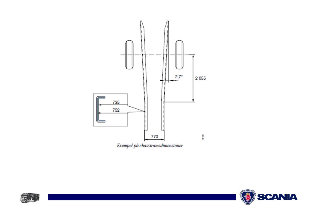
Chassisrammer

3
Chassisrammer

4
Fabrikanterklæring Det kan hermed bekræftes, at Scania`s chassisrammer kan belastes som følger. Generelt: Tilladelig spænding fra opbygning og last, tillades 150 N/mm2. (Statisk beregning). Belastning under stilstand med bidrag fra hjælpeudstyr som kran: Tilladelig spænding 300 N/mm2. (Total belastning ved statisk beregning). Ved fremlæggelse af specifik beregning har vi mulighed for at acceptere 315 N/mm2
. Belastning under stilstand med bidrag fra hjælpeudstyr som kran: Tilladelig spænding 300 N/mm2. (Total belastning ved statisk beregning). Ved fremlæggelse af specifik beregning har vi mulighed for at acceptere 315 N/mm2.")
5
Ikke bore hul i over- eller underflange
Svejsning: Undgå svejsning mellem akslerne Akselafstandsændring - flyt ophæng Svejsning bagud - tillades under ansvar Min. 350 mm bag sidste aksel Ikke bore hul i over- eller underflange

6
Svejsning Svejsetemperatur maks C Minuspol demonteret Stel så tæt på svejsestedet som mulig Sørg for god stelforbindelse Afdækning for sprøjt (fjedre m.v.)
")
7
Spoiler Tænk på brændstoføkonomi! Reduktion i luftmodstand:
Tagspoiler - 10% Tag- side spoiler – 35%

8
Bolteforbindelser Friktionssamling: M14 kl. 8.8, 135Nm, bor ø 14,8 mm
Kræver flere beregninger og skruer Overklipning pasbolt med bryst M14 kl. 8.8, bor ø 13,8 mm M16 kl. 8.8, bor ø 15,8 mm Indbygget sikkerhed

9
Befæstigelse af hjælperamme

10
Svingninger-rystelser
Se opbygger bog Beregning og Teori

11
Svingninger-rystelser

12
Liftmontering 4x2 chassis: Afstand til drivaksel 3000 mm 6x2 chassis:
Enkeltramme maks. løftekapacitet 1500 kg. Pas på! Lifte op til 2500 kg, altid beregning. Pas på! Tænk også på vridning. (evt. kryds)
")
14
Liftmontering

15
Liftmontering 4x2 chassis: Afstand til drivaksel 3000 mm .
2,5 ton lift KRÆVER kryds i overhæng

16
Liftmontering

17
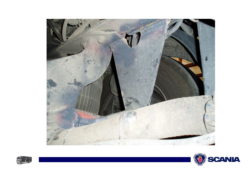
Hvad er det ?

18
Hvad er det ?

19
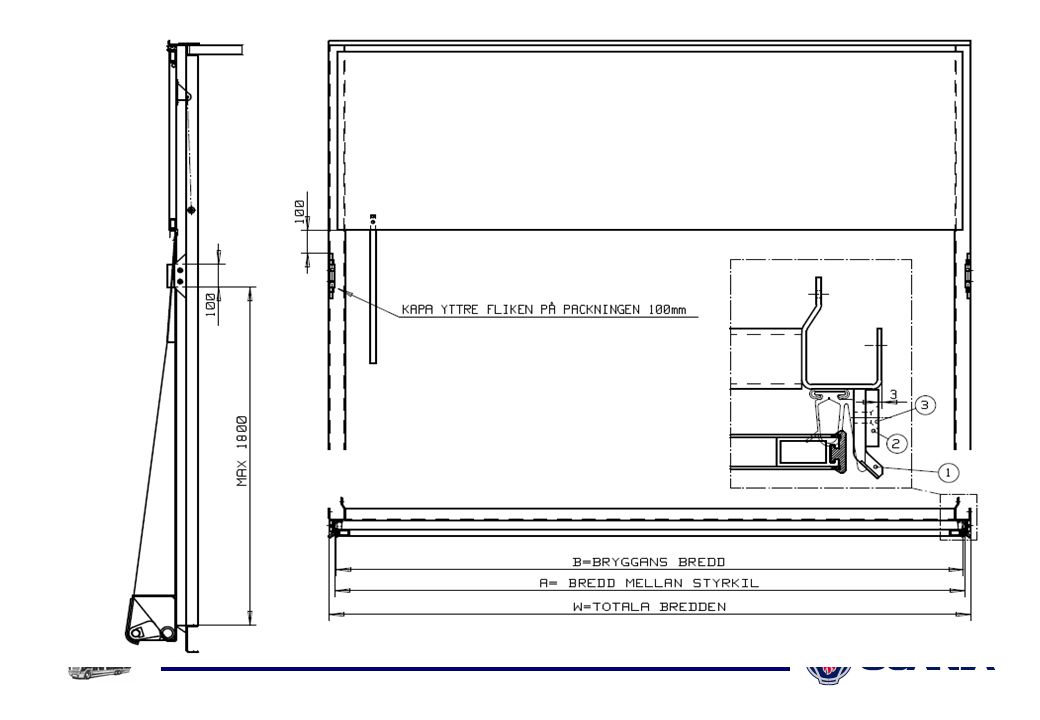
5. Skruva fast detalj 1 i detalj 2 med medföljande skruvar
1. Ta bort gummilisten 2. Svetsa fast detalj 2 i karmen minst 3 mm in från yttre ytan (se ritning). Kontrollera mot mått A på ritningen 3. Montera gummilisten 4. Kapa bort ca 100 mm av den yttre fliken på gummilisten vid styrkilen (se ritning) 5. Skruva fast detalj 1 i detalj 2 med medföljande skruvar 6. Granska vid dörrsidan så att dörrbladet på sidodörren inte kolliderar med styrkilen när dörren öppnas (Bilder är bifogade när detta monteras på en ny bakport)
. Kontrollera mot mått A på ritningen. 3. Montera gummilisten. 4. Kapa bort ca 100 mm av den yttre fliken på gummilisten vid styrkilen (se ritning) 5. Skruva fast detalj 1 i detalj 2 med medföljande skruvar. 6. Granska vid dörrsidan så att dörrbladet på sidodörren inte kolliderar med styrkilen när dörren öppnas. (Bilder är bifogade när detta monteras på en ny bakport)")
20
Detalje 1 Detalje 3 Detalje 2

21
Svetsa fast detalj 2 i karmen minst 3 mm in från yttre ytan (se ritning).
Kontrollera mot mått A på ritningen.

22
Skruva fast detalj 1 i detalj 2 med medföljande skruvar

27
ESP The yaw rate sensor includes two bulk micromachined oscillating masses where each of them supports two surface micromachined accelerometers for detection of the coriolis acceleration. The measurement principle is based on the coriolis force imposed by a rotation (yaw rate) orthogonal to the given oscillation direction of the seismic masses. The effect of this coriolis force is measured by the difference between the output of the two accelerometers. The acceleration is measured by an additional micromachined accelerometer. Calibration of the Yaw Rate Sensor After power on sensor offset calibration of the yaw rate sensor is done to enable the ESP although with extended intervention bands. Therefore in normal cases (power on and vehicle at rest) a standstill calibration is performed, while in special cases (power on and moving vehicle) a fast calibration takes place. The calculated offset is monitored and continuously compared with the allowed threshold value. After this first calibration of the yaw rate sensor the standard calibration process runs while the vehicle is moving. a) Standstill Calibration The standstill calibration is executed if standstill is detected by monitoring the wheel speeds, steering angle and yaw rate. This calibration is interrupted if driving is detected before the calibration is finished. The calculated offset is checked continuously to the allowed threshold value. b) Fast Calibration The fast calibration process runs only once per power on cycle and only if no standstill calibration could be done before. The offset is identified via a algorithm using the difference between the sensor signal and a calculated reference yaw rate as inputs. Again this identified offset is monitored and continuously compared with the allowed threshold value. c) Normal Calibration After a standstill calibration or a fast calibration was done, a normal calibration during regular operation is performed. The normal calibration process is similar to the fast calibration process d) Sensor Sensitivity Calibration The sensitivity of the sensor is identified during a curve-drive by an algorithm using a calculated reference yaw rate and the measured sensor signal as inputs.
 orthogonal to. the given oscillation direction of the seismic masses. The effect of this coriolis force is measured by. the difference between the output of the two accelerometers. The acceleration is measured by an additional micromachined accelerometer. Calibration of the Yaw Rate Sensor. After power on sensor offset calibration of the yaw rate sensor is done to enable the ESP although. with extended intervention bands. Therefore in normal cases (power on and vehicle at rest) a standstill. calibration is performed, while in special cases (power on and moving vehicle) a fast calibration takes. place. The calculated offset is monitored and continuously compared with the allowed threshold value. After this first calibration of the yaw rate sensor the standard calibration process runs while the vehicle. is moving. a) Standstill Calibration. The standstill calibration is executed if standstill is detected by monitoring the wheel speeds, steering. angle and yaw rate. This calibration is interrupted if driving is detected before the calibration is. finished. The calculated offset is checked continuously to the allowed threshold value. b) Fast Calibration. The fast calibration process runs only once per power on cycle and only if no standstill calibration. could be done before. The offset is identified via a algorithm using the difference between the sensor. signal and a calculated reference yaw rate as inputs. Again this identified offset is monitored and. continuously compared with the allowed threshold value. c) Normal Calibration. After a standstill calibration or a fast calibration was done, a normal calibration during regular. operation is performed. The normal calibration process is similar to the fast calibration process. d) Sensor Sensitivity Calibration. The sensitivity of the sensor is identified during a curve-drive by an algorithm using a calculated. reference yaw rate and the measured sensor signal as inputs.")
28
Førerhus Mekanisk ophæng - justerbar forspænding

29
4-Bælg ophæng Tyndere chassisramme F700 Nyt hulbillede i chassis, modulhul

30
Højt placeret brændstoftank

31
Højt placeret brændstoftank

32
Højt placeret brændstoftank

33
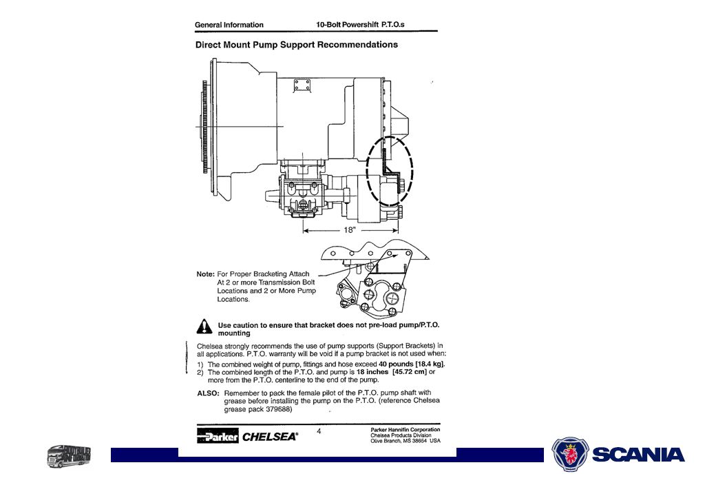
Maksimal pumpevægt på Allison gearkasser

35
Montering af pumpe på EG

36
Montering af pumpe på ED

37
Montering af pumpe på ED

38
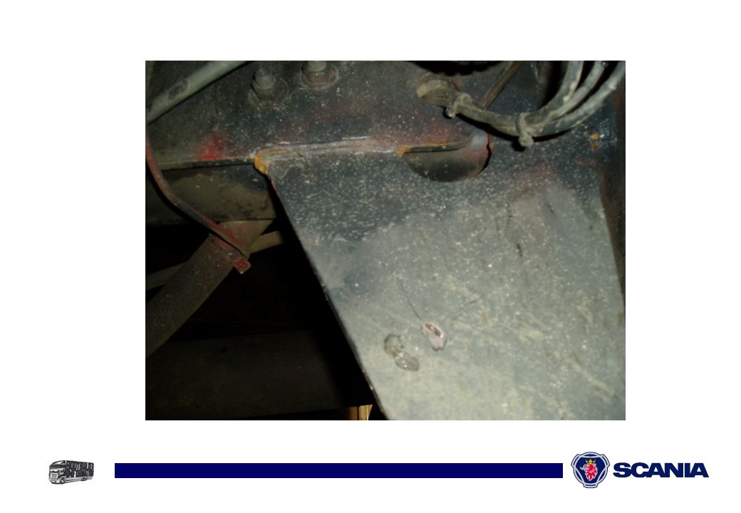
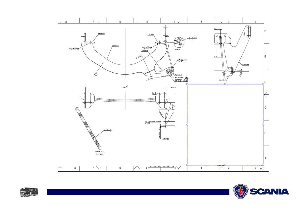
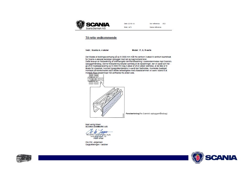
Træktøj på bagsiden af kran
Erklæring vedlagt

40
Varm udstødning

41
Varm udstødning

42
Varm udstødning

43
Ombygning af udstødning
EGR flytning til bag 2 aksel OK

44
Ombygning af udstødning
AdBlue-tank må flyttes

45
Ombygning af udstødning
Euro4 og Euro5 som anvender AdBlue: På biler, der anvender SCR-teknikken, det vil sige tilsætning af AdBlue, er det ikke tilladt at flytte lyddæmperen. Flyttes lyddæmperen fra den position, hvor fabrikken har placeret den, bortfalder reklamationsretten på skader, der kan henføres til denne flytning. SCR-lyddæmper må IKKE flyttes

Lignende præsentationer